
BOF Converter Refractory Lining Solutions
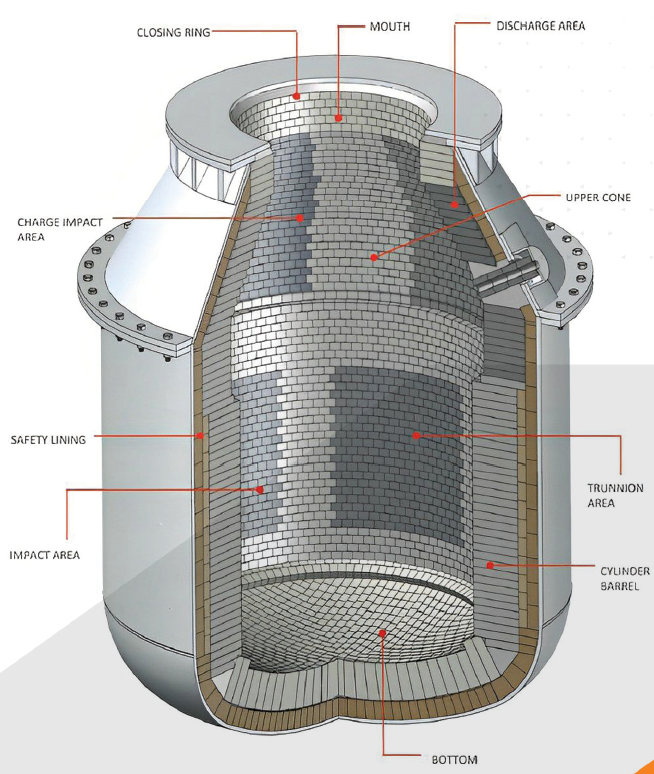
STA Commerce supports international enquiries for basic oxygen furnace (BOF) converter refractory lining products. The documented scope includes zoned working and safety linings for converter areas such as the mouth, upper cone, discharge, impact, trunnion, barrel and bottom; technical requirements are coordinated with relevant refractory suppliers.
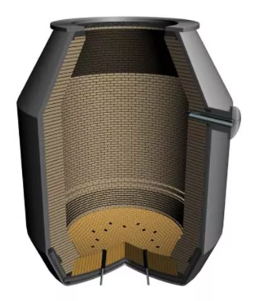
Protecting the Converter Throughout the Production Campaign
The purpose of the refractory lining in a basic oxygen furnace is to maintain maximum converter availability while meeting production requirements and controlling refractory consumption.
Different areas of the converter experience different combinations of heat, slag corrosion, metal impact, charging damage and mechanical stress. A zoned lining concept allows the refractory system to be adapted to these local conditions.
Required Performance of BOF Converter Refractories
Main BOF Converter Refractory Zones
The vessel is divided into distinct zones so that each area can receive a refractory quality and thickness suitable for its operating exposure.
Zoned Refractory Design for Converter Availability
Working Lining
The hot-face lining directly contacts molten metal, slag and process gases and is selected according to the wear severity of each zone.
Safety Lining
The permanent backup layer supports the working lining and provides additional protection for the converter shell.
Zone-Specific Materials
Brick chemistry, carbon level, density and shape can be adjusted to the impact, corrosion and thermal demands of each converter area.
Typical Lining Considerations by Converter Area
| Converter Area | Typical Exposure | Main Lining Function |
|---|---|---|
| Mouth, Closing Rings & Upper Cone | Thermal cycling, slag splash, mechanical handling and upper-vessel wear. | Maintain dimensional stability and protect the upper vessel structure. |
| Charge Impact & Impact Areas | Scrap charging, mechanical shock and localized abrasion. | Resist impact and maintain working-lining integrity. |
| Discharge Area | Molten-metal and slag flow during tapping. | Resist erosion, chemical wear and repeated flow exposure. |
| Trunnion Area & Cylindrical Barrel | Slag corrosion, metal contact and repeated process cycles. | Provide balanced corrosion and structural resistance. |
| Bottom | High thermal loading, bath contact and structural stress. | Support the vessel bath zone and protect the lower shell. |
| Safety Lining | Secondary exposure behind the working lining. | Provide backup protection and structural support. |
Information Needed for Lining Design and Supply
Complete technical and operating information is required to prepare a zoned refractory recommendation. Confirm final grade and product specifications with the relevant refractory supplier against approved lining drawings and operating conditions.
Related BOF Lining Materials
For working-lining and high-wear converter zones, see our BOF MgO-C refractories.
Request a BOF Converter Refractory Quotation
Send us the converter model, lining drawings, operating practice, current refractory grades, required quantity and destination country for technical and commercial review.